
Views: 0 Author: Site Editor Publish Time: 2026-08-26 Origin: Site


Tooling accounts for roughly 3% of total production costs in most CNC machining environments. However, selecting the wrong tool easily bottlenecks the other 97% of your operation. Poor tool choices directly cause unexpected machine downtime, unacceptable surface finishes, and heavily scrapped parts. You need a systematic framework to avoid these expensive production traps. This guide helps engineers and shop managers transition away from pure guesswork. It moves your team toward highly data-driven tooling procurement.
Mastering this process requires carefully balancing substrate grades, edge geometry, and specific application demands. You must always aim to achieve the lowest true cost-per-part. Simply hunting for the cheapest upfront cost-per-insert rarely yields operational success. By aligning your tooling choices with real-world machining conditions, you maximize machine output. You also stabilize your overall cutting processes. We will explore exactly how to evaluate and select the best tools for your shop floor.
Insert shape dictates edge strength and accessibility; standardizing on specific shapes (like WNMG or CNMG) can reduce inventory overhead and maximize cost-per-edge.
Grade selection must align with the ISO material group (P, M, K, etc.) and prioritize either wear resistance (CVD) or edge toughness (PVD) based on machining conditions.
Chipbreaker geometry is non-negotiable for unattended machining—matching the chipbreaker to your depth of cut (DOC) and feed rate prevents catastrophic tool failure.
The optimal turning insert is validated through controlled, data-backed floor testing rather than catalog promises.
You must shift your focus entirely away from the upfront price tag. A single carbide insert might seem like a bargain initially. However, poor cutting performance quickly ruins your cycle times. We must evaluate its actual impact on overall machine utilization. An unreliable tool forces operators to constantly stop the spindle. This halts production and destroys profitability.
We need to define exactly what a successful application looks like. Success requires highly predictable tool life first and foremost. You cannot automate a process if the tool fails randomly. You also need reliable chip control to keep the cutting zone clear. Finally, strict dimensional stability is required to keep parts within tolerance limits.
Evaluating cost-per-edge alone remains a flawed metric. Productivity matters significantly more in modern manufacturing. Running a harder tooling grade at higher surface footage (SFM) accelerates your part production. You will buy replacement tools more frequently. However, you will often yield a much higher overall return on investment. The increased hourly part output heavily outweighs the minor extra tooling expense.
Insert shape governs both versatile application limits and fundamental edge strength. We use the standard ISO nomenclature to understand these properties. The first letter (C, W, D, V) dictates the included angle of the cutting edge. Larger included angles provide incredibly robust cutting edges. Smaller angles offer much better clearance but lack structural integrity.
Consider the heavyweight battle in general turning applications. The CNMG insert features a standard 80-degree rhombic shape. It delivers exceptional high strength. Shop managers consider it excellent for heavy roughing and aggressive facing operations. Now, compare it directly against the popular WNMG insert. This tool features an 80-degree trigon shape.
Shortlisting logic often favors the trigon design strictly for manufacturing economy. The WNMG boasts six usable edges versus four on the CNMG design. You maintain the exact same 80-degree included angle for robust roughing. Yet, you gain 50% more cutting edges per purchase. This drastically lowers your tooling spend for standard turning operations.
Sometimes you face severe accessibility constraints. Deep profiling and intricate undercutting require stepping down to weaker, more acute angles. A D-style 55-degree or V-style 35-degree shape easily reaches into tight corners. They inevitably sacrifice basic edge strength for necessary clearance. Use them only when the specific part geometry absolutely demands it.
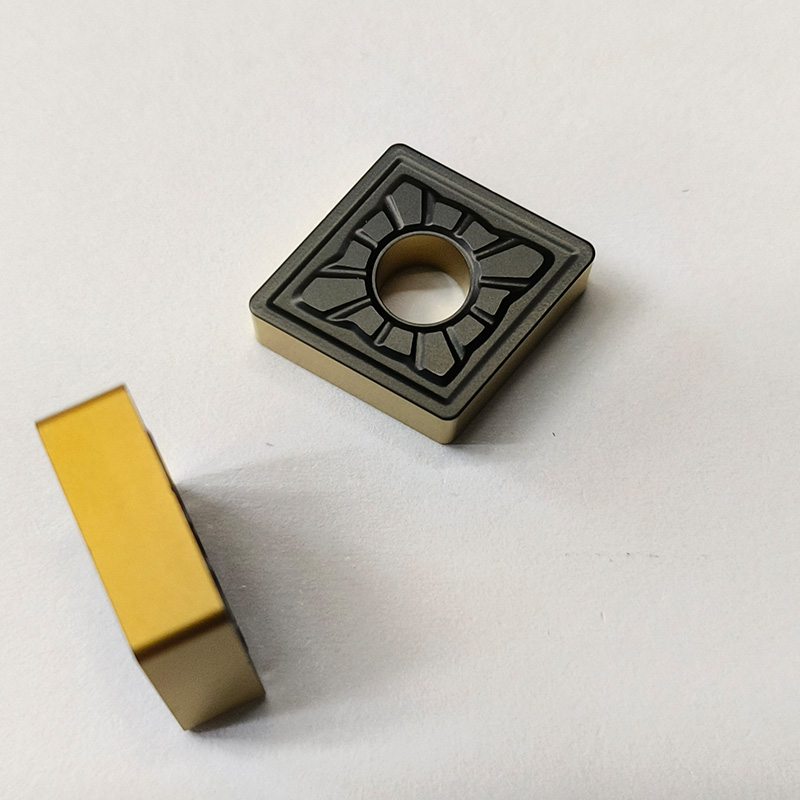
Grade selection directly determines how a tool handles heat and friction. You must categorize these solutions by their substrate materials and applied coating technologies. Correct workpiece material alignment dictates your long-term success.
ISO P materials, like standard carbon steel, generate intense heat. They cause severe crater wear on the top of the cutting edge. They require grades specifically optimized to resist thermal degradation. You will typically rely on Chemical Vapor Deposition (CVD) coatings to survive these conditions.
ISO M (Stainless Steel) and ISO S (Heat-Resistant Super Alloys) behave very differently. They cause rapid work hardening during the cut. These difficult materials demand heat resistance combined with sharp, tough cutting edges. Physical Vapor Deposition (PVD) coatings usually excel in these harsh, gummy environments.
ISO K (Cast Iron) creates highly abrasive, powdery chips. You need substrate grades boasting superior abrasive wear resistance to maintain edge integrity over long runs.
Use this clear coating decision matrix to guide your shop floor:
Select CVD coatings for high-speed, continuous roughing operations where heat is extreme.
Select PVD coatings for interrupted cuts, fine finishing passes, or very sticky materials.
We must warn you against manufacturers claiming they offer a true "universal grade." Evidence shows these tools rarely optimize production effectively. A tool perfectly tuned for Inconel will severely underperform on mild steel. It will also cost far too much for that application. Always match the specific ISO material class to a dedicated grade designed for it.
Macro-geometry involves the basic shape and clearance angle. Micro-geometry refers directly to the engineered chipbreaker groove. You must connect these features strictly to your specific machining application. Roughing, medium turning, and finishing each require distinctly different geometries.
Proper chip control remains an absolute imperative on the shop floor. An incorrect chipbreaker produces long, stringy chips. They rapidly wrap around the chuck and the spinning workpiece. This poses severe safety hazards for operators. It also completely halts automated robotic loading systems.
You must map your intended depth of cut (DOC) and feed rate correctly. Compare your baseline parameters against the manufacturer's recommended operating window. Running outside this window guarantees failure.
Chipbreaker Operating Window Comparison
Operation Type | Depth of Cut (DOC) | Feed Rate | Chipbreaker Characteristic |
|---|---|---|---|
Roughing | High (0.100"+) | High | Wide, deep grooves designed to fracture thick material |
Medium Turning | Moderate | Moderate | Balanced groove geometry for general versatility |
Finishing | Low (Under 0.020") | Low | Narrow, tight grooves built to aggressively curl thin chips |
Consider implementing wiper technology for serious production scalability. Wiper geometries feature a highly specialized trailing edge. They allow shops to double feed rates without sacrificing strict surface finish requirements. This micro-geometry drastically boosts your throughput on large production runs.
Transitioning to new tooling always introduces several implementation risks. Operator hesitation is extremely common when changing established processes. You will likely produce some initial scrapped parts during the setup phase. Unpredictable machine dynamics, such as poor spindle rigidity, also complicate tooling trials.
You can mitigate these risks using a rigid, three-step controlled test protocol.
Establish your current machining baseline. Document the exact SFM, feed rate, DOC, and tool life measured in minutes or completed parts.
Run the new turning insert selection guide recommendations exactly at your established baseline first. Once the process proves stable, carefully scale up the parameters to match the manufacturer specifications.
Document any tool failure modes under strict magnification. Identify whether the tool failed from normal flank wear or catastrophic chipping.
Maintain transparency regarding standard catalog assumptions. Published speeds and feeds assume perfectly rigid setups and optimal coolant delivery. Real-world applications rarely match pristine lab conditions. They usually require a 10% to 20% conservative starting adjustment. Always prioritize process stability over initial speed.
You need actionable next steps to simplify this procurement process. Synthesize these technical concepts into a rapid evaluation checklist. Follow this exact sequence to consistently find the ideal tool.
Step 1: Identify the exact ISO workpiece material classification (P, M, K, N, S, H).
Step 2: Determine the specific operation type. Clarify if you need roughing, finishing, continuous cutting, or interrupted cutting.
Step 3: Select the strongest insert shape the part profile allows. A standard turning insert like an 80-degree rhombic offers immense strength.
Step 4: Pick a corresponding chipbreaker based strictly on your target DOC and feed rate parameters.
Step 5: Select the ideal grade and coating technology. Balance the fundamental need for high wear resistance against the mechanical need for toughness.
Following this checklist removes pure emotion and guesswork from your procurement strategy. It relies entirely on proven mechanical and material science principles.
An optimal tooling strategy successfully merges advanced material science with practical mechanical design. Selecting the right grade and geometry directly lowers costly production bottlenecks. It keeps your spindles running efficiently and ensures chips break cleanly.
Avoid buying tools purely based on shiny digital catalogs. We highly encourage partnering directly with tooling application engineers. They offer invaluable insights for complex materials and highly challenging setups. They also help troubleshoot unpredictable machine dynamics quickly.
Take action today to improve your processes. Contact a tooling specialist to discuss your toughest turning applications. Request physical test samples to run through the three-step controlled protocol. Use an interactive tooling selector tool to build a highly data-driven shortlist for your next major production run.
A: The primary difference lies in their shape and resulting economy. Both feature an 80-degree included cutting angle, making them exceptionally strong for robust roughing. However, a CNMG utilizes a rhombic shape offering four usable edges. A WNMG utilizes a trigon shape offering six usable edges. This gives the trigon a distinct economic advantage for general turning operations.
A: You should select a PVD coating when you need extremely sharp cutting edges, process interrupted cuts, or machine gummy materials like stainless steel. PVD provides high edge toughness. Conversely, select a CVD coating for high-speed, continuous roughing where you need a much thicker thermal barrier against extreme heat.
A: Always check the tooling manufacturer’s specific feed and depth-of-cut (DOC) chart. Roughing operations require wide and deep breakers to safely handle thick material removal. Finishing operations require narrow, tight breakers to aggressively curl and break very thin chips.
A: Premature chipping usually stems from mechanical failures rather than normal abrasive wear. Common culprits include a severe lack of setup rigidity, running a feed rate far too low for the selected chipbreaker, or using a carbide grade that is simply too hard and lacks the necessary toughness for an interrupted cut.


