
Views: 0 Author: Site Editor Publish Time: 2026-08-31 Origin: Site


Modern machining demands absolute precision and reliability. Rushing into production without verifying your tooling choices is a dangerous gamble. Bypassing insert verification before a large run exposes your shop to severe operational risks. You might experience catastrophic tool failure, scrap expensive parts, or suffer unpredictable machine downtime. These issues destroy profit margins instantly. Conversely, a successful pre-production check establishes a highly reliable foundation. It guarantees predictable tool life, an optimized cost-per-part, and extremely stable chip control.
Our objective is to give you a definitive, step-by-step evaluation framework. Machinists and production managers can use this protocol to validate insert selection before scaling up operations. By following these exact steps, you will eliminate guesswork and maximize machining efficiency. Establishing control over your turning process begins long before the spindle turns.
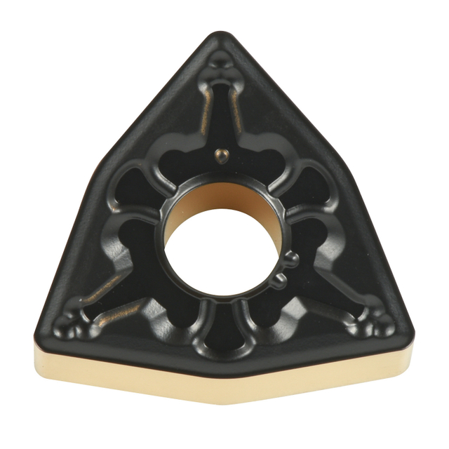
Always match the ISO material classification (P, M, K, N, S, H) to the specific workpiece alloy to prevent rapid edge deterioration.
Verify exact ANSI/ISO code compatibility with the existing tool holder to ensure rigid clamping and positional accuracy.
Select chipbreaker geometry based strictly on the required depth of cut and feed rate (roughing vs. finishing).
Assess the coating type (CVD vs. PVD) against the thermal and mechanical realities of your specific CNC environment.
Run controlled baseline tests to establish verifiable tool life metrics before running unattended production.
Many tooling suppliers market "universal" inserts to simplify purchasing. A universal insert is a massive liability in high-volume production. It forces you into a mechanical compromise. It might cut both aluminum and steel adequately. However, it will never perform optimally on either. In production, sub-optimal performance translates directly into lost revenue and erratic tool wear.
You must establish a strict material baseline. The machining industry relies on standardized ISO material groups to categorize workpiece materials. Evaluating a turning insert for steel (ISO P) requires entirely different criteria than evaluating one for stainless steel (ISO M) or cast iron (ISO K). Each material group dictates distinct demands on the cutting edge.
ISO P (Steel): Generates long chips and high crater wear.
ISO M (Stainless Steel): Prone to work hardening and built-up edge.
ISO K (Cast Iron): Produces short, abrasive chips causing severe abrasive wear.
ISO S (Heat-Resistant Superalloys): Generates massive localized heat.
Failing to match the insert to the ISO classification carries severe consequences. Imagine using an ISO K insert on a high-temperature titanium alloy. You will almost certainly experience catastrophic thermal cracking. The carbide substrate lacks the necessary heat resistance. Conversely, using a highly heat-resistant ISO S grade on soft aluminum causes built-up edge (BUE). The material welds itself to the cutting edge, destroying surface finish and eventually fracturing the insert.
Every cutting tool utilizes a standardized alphanumeric code. You must decode this system systematically to ensure perfect compatibility. This code defines every physical characteristic of the insert. It dictates shape, clearance angle, tolerance, type, size, thickness, and corner radius.
Common Mistakes: Ignoring the clamping mechanism when selecting your tool. The way a turning insert secures into the pocket dictates its suitability for specific operations. A simple screw-on clamp works fine for light finishing. However, heavy roughing or high-vibration applications demand a rigid lever lock or rigid clamp system. A lever lock pulls the insert securely against the pocket walls. This prevents micro-movements during heavy interrupted cuts.
You must also evaluate the dimensional tolerance class. This is usually the third letter in the standard ISO code (e.g., the 'M' in CNMG or the 'G' in CNGG). The tolerance class defines the allowable dimensional variation from insert to insert.
Best Practice: Always check this third letter for precision tasks. For tight-tolerance finishing operations, a 'G' class insert offers significantly tighter precision than an 'M' class. Ensuring your insert's precision matches the required part specs prevents constant machine offsets during index changes.
Position Number | Physical Characteristic Defined | Practical Implication for Production |
|---|---|---|
1 | Insert Shape (e.g., C, D, T) | Determines cutting edge strength and clearance. |
2 | Clearance Angle (e.g., N, P) | Dictates whether the tool is positive or negative. |
3 | Tolerance Class (e.g., M, G) | Controls dimensional repeatability between indexes. |
4 | Fixing/Chipbreaker Type | Identifies mounting style and hole configuration. |
5-7 | Size, Thickness, Radius | Must perfectly match the tool holder pocket. |
Chipbreaker geometry is arguably the most critical factor for reliable unattended machining. You must align the application strictly with the correct geometry. Manufacturers design specific geometries for roughing, medium turning, and finishing operations. You cannot swap them interchangeably.
A reliable CNC turning insert relies heavily on these specific designs to evacuate chips efficiently. Proper evacuation prevents chips from wrapping around the workpiece or the chuck. When chips fail to break, they cause recutting. Recutting immediately destroys the surface finish and often shatters the cutting edge.
You must select chipbreakers based strictly on Depth of Cut (DOC) and feed rate. Different geometries activate at different parameters.
Roughing Geometries: Designed for heavy feed rates and deep cuts. They have wide, open grooves.
Finishing Geometries: Designed for light feeds and shallow cuts. They feature tight, narrow chip curl areas.
If you use a heavy roughing chipbreaker at a very shallow DOC, the chip will never hit the back wall of the breaker. It will simply spool off as a long, dangerous string. Furthermore, a roughing geometry pushed at low feeds will generate excessive cutting pressure. This pushes the tool off the part, causing dimensional taper and poor surface finishes.
Selecting the right grade requires balancing substrate toughness against hardness. This is a fundamental trade-off in materials science. Harder grades resist abrasive wear brilliantly. However, they are brittle. They will chip instantly under interrupted cuts or high vibrations. Tougher grades absorb impact and survive interrupted cuts seamlessly. Yet, they wear down much faster in continuous, high-speed turning.
You must evaluate coating technologies against your specific thermal realities. Modern coatings generally fall into two categories: CVD and PVD.
CVD (Chemical Vapor Deposition): These coatings are thick and highly wear-resistant. They act as an excellent thermal barrier. We use CVD primarily for high-speed, high-heat continuous turning. The thickness provides incredible protection for the substrate.
PVD (Physical Vapor Deposition): These coatings are much thinner. They adhere well to very sharp cutting edges. PVD is ideal for finishing operations, interrupted cuts, or gummy materials like aerospace alloys. The thinner coating prevents edge blunting.
Implementation Consideration: Always audit your coolant usage before selecting a Carbide Turning Insert. Thick CVD coatings retain massive amounts of heat. If your coolant application is inconsistent, the cutting edge experiences rapid temperature fluctuations. This thermal shock causes thick CVD coatings to crack and shatter prematurely. Sometimes, running dry is actually safer for CVD grades than applying poor coolant.
You cannot blindly trust catalog parameters. Manufacturer-recommended Surface Feet per Minute (SFM) and feed rates serve only as baseline metrics. You must evaluate these numbers against the harsh realities of your own machine. A lightweight lathe cannot push the same heavy feed rates as a rigid box-way turning center. If you lack the necessary horsepower or rigidity, you must scale down the parameters to prevent chatter.
Next, you must shift your focus entirely away from the initial purchase price. Buying cheap carbide often ruins production economics. Instead, evaluate predictable tool life and reduced machine downtime. A highly reliable tool allows operators to run multiple machines simultaneously. A cheap, unpredictable tool forces operators to hover over the control panel.
In high-volume production, predictability trumps maximum lifespan. Predictable flank wear is infinitely more valuable than erratic tool life. If a tool lasts exactly 45 minutes every single time, you can program an automatic tool change at 40 minutes. You eliminate scrap entirely. If a cheaper tool lasts anywhere between 20 and 60 minutes randomly, you will inevitably scrap parts when it fails early.
Never commit to a 10,000-part production run based on a manufacturer's brochure. You must establish a rigid testing framework. We strongly recommend executing a pilot run first. A pilot run of 10 to 50 parts provides invaluable real-world data.
Follow this specific testing protocol for your pilot run:
Document the Baseline: Record current cycle times, scrap rates, and tool change frequencies.
Set Controlled Parameters: Lock in the spindle speed, feed rate, and DOC. Do not allow operators to tweak overrides during the test.
Run the Pilot Batch: Machine the 10 to 50 parts consecutively without stopping unless catastrophic failure occurs.
Conduct Failure Analysis: Remove the tool and inspect it closely.
Failure analysis is the most critical step. You must inspect the cutting edge under a 10x or 20x jeweler's loupe. Look specifically for the wear pattern. Normal flank wear indicates a stable, predictable process. Deep crater wear suggests excessive heat. Micro-chipping points to an overly hard substrate or a feed rate that is too aggressive. Plastic deformation means you are pushing the tool far beyond its thermal limits.
Apply strict final decision logic. Do not approve the tool just because it survived. The carbide turning insert must meet all surface finish requirements consistently. It must evacuate chips reliably without operator intervention. Finally, it must show predictable wear patterns at your target cycle times. If it passes these three gates, you can safely approve it for full-scale production.
Successful high-volume machining requires intense preparation. You must align your tooling geometry, grade, and coating directly with your operational realities. Neglecting material compatibility or chipbreaker mechanics guarantees erratic performance. Testing parameters in a controlled pilot run protects your profitability.
Take action before your next major job begins. Audit your current tooling setups against this exact checklist. Look for mismatches between your ISO grades and your actual workpiece materials. If you encounter persistent wear issues, consult your tooling provider immediately. Request specific grade and geometry recommendations tailored to your machine's rigidity and coolant capabilities. Proactive validation always outperforms reactive troubleshooting.
A: Look for sudden changes in surface finish, increased spindle load, unpredictable chip shapes, or audible chatter. These indicators suggest the cutting edge is compromised. Rapid loss of dimensional tolerance on the workpiece also clearly signals premature wear. Do not wait for complete fracture; pull the tool and inspect it under a loupe.
A: While possible in low-volume job shops, production environments require dedicated geometries to ensure cycle time efficiency and dimensional accuracy. Roughing requires strong edges and open chipbreakers. Finishing requires sharp edges and tight chip control. Mixing them compromises both surface quality and tool life.
A: Usually indicates the carbide grade is too hard, the feed rate is too high, or the edge prep is too sharp. Harder grades lack the toughness to absorb impacts. Transitioning to a tougher substrate or a PVD-coated insert often resolves this. Ensure your clamping mechanism is fully rigid.
A: There is no universal standard; it is measured in time-in-cut (typically 15-45 minutes per edge) depending on the material, speed, and acceptable wear margins before part tolerances drift. Predictability matters far more than maximum lifespan. Establish your own baseline during a controlled pilot run.


